The Pool Overflow Prevention (P.O.P.) Valve Story
Hi, my name is John.
This is me
Problem
This idea started about a month ago when I was talking to my friend Jake. He told me about a time he left a hose running in his pool right before a party, only to find it had overflowed, creating a huge mess. That story stuck with me. I remembered when my family had a pool, and my dad would constantly tell me to go outside every hour and check the water level because he was worried about it overflowing. It was tedious and easy to forget—and I realized it’s a common problem.
Dramatic AI reenactment of the pool overflowing
Jake definitely had this problem, but was it a real issue or a Jake issue? To see, I texted my friend Frankie, who’s known for being brutally honest. He thought it might actually be a good idea, so I reached out to another friend who works in pool sales. He confirmed that overfilling is more common than people admit, and he even has to regularly explain how to drain pools to frustrated customers. That’s when I knew I had something worth pursuing.
The Solution
Surprisingly, the moment I registered the problem, the solution hit me like a bolt of lightning, and I thought for sure this had been done before. In fact... nope, the idea was to design a simple, automatic way to prevent pool overflow using principles similar to gas station nozzles, and apparently it hasn't been done yet. (My dad is still shocked.)
V1 for CFD testing
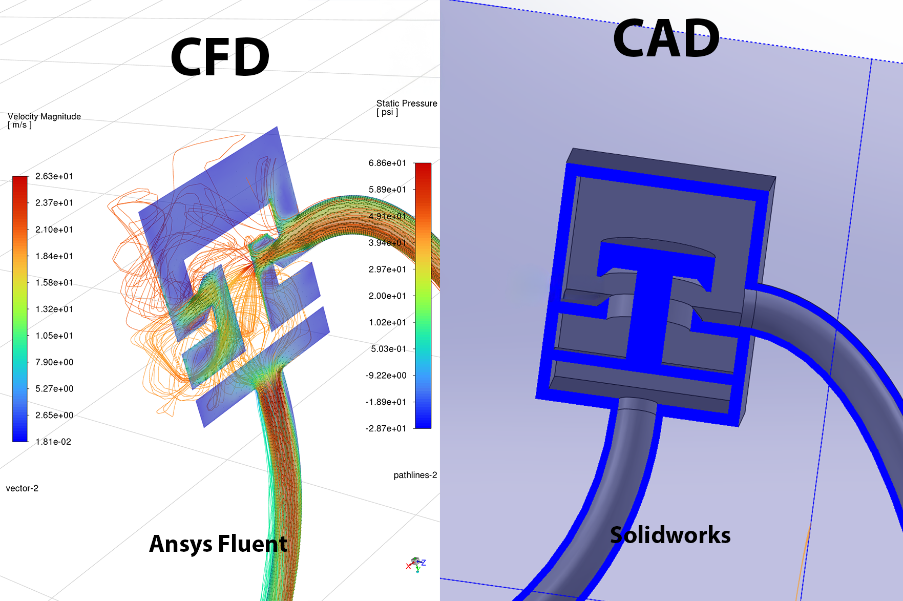
The first thing I needed to know was the required spring strength for the shut-off valve so to ANSYS Fluent.
The picture on the left is a computer simulation where I told my computer to estimate the path that the water
would follow, hence pathlines, and the speed of the water at "all" points shown by the semi-transparent gradient.
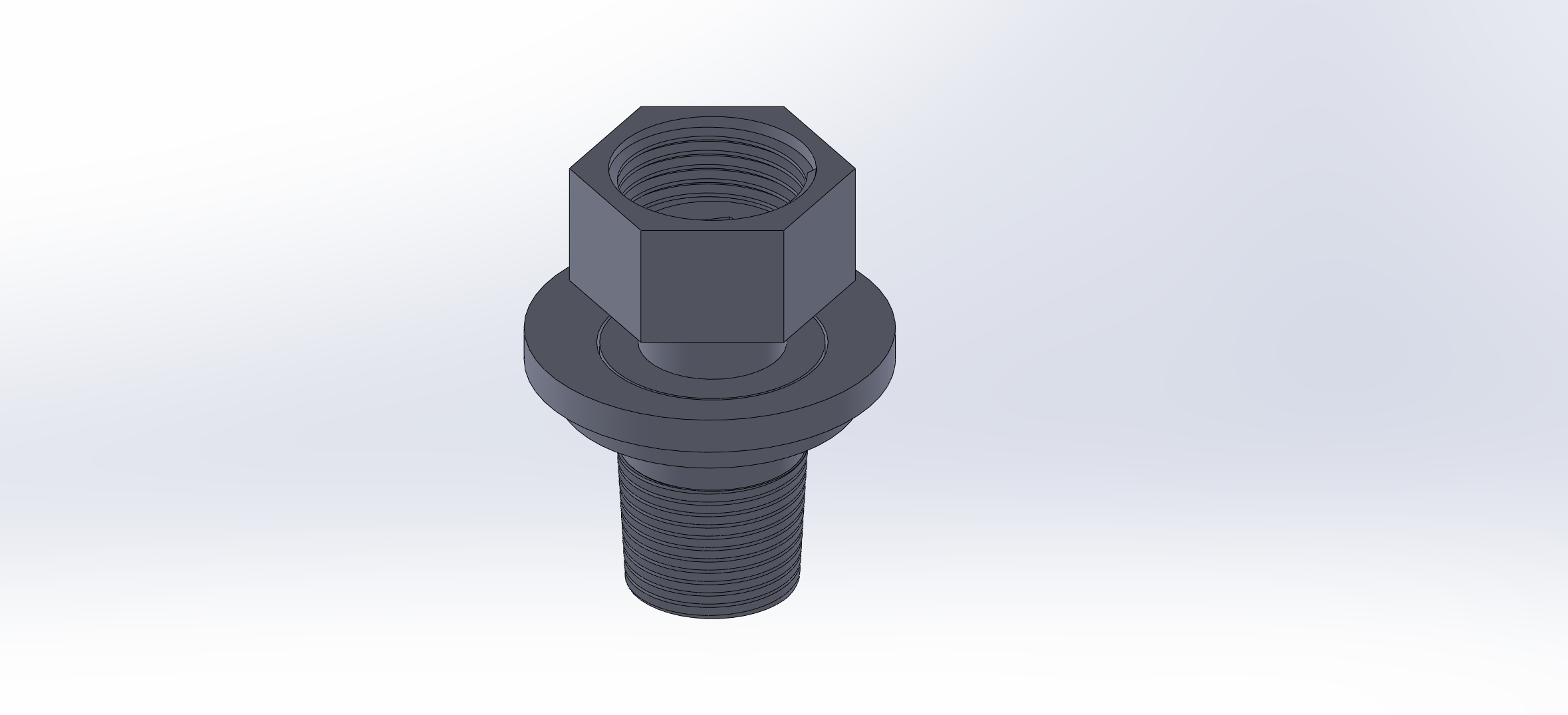
On the right is the CAD model for reference on what V1 looked like. (Neither of these shows the actual
spring calculation, which is about 0.5N.)
V1 Validation testing
This valve barely counts as working, but that’s expected right now. When it’s open,
the top pressure drops more than when it’s closed, so it’s kind of acting like a
bad splitter. Still, that’s what I figured would happen, and I’m happy to see it at this stage.
problems:
It’s not sealed.
It doesn’t fit on the hose.
Water is coming out of the bottom near the actuator.
There is no spring yet.
I'm going to skip the two versions in between V1 and V4
V4: What changed and why
The first change was in the shape because I ran a finite element analysis and found this.
This indicates that, in theory, the original could probably hold the water (since technically the tensile strength
is higher the the max stress), but it would bulge. Therefore, I decided to redesign it to make the internal pressure
closer to the part's strength, which reduced the deflection by 66.35%. Additionally, what is less obvious from the
picture is that this change also decreased the material usage by 18.35%.
After that, I added a spring to make it automatically close, and then an O-ring to hopefully seal it.
This is a cross-sectional view, so this is what it would look like if I cut it in half.
Did all of that work? Well...
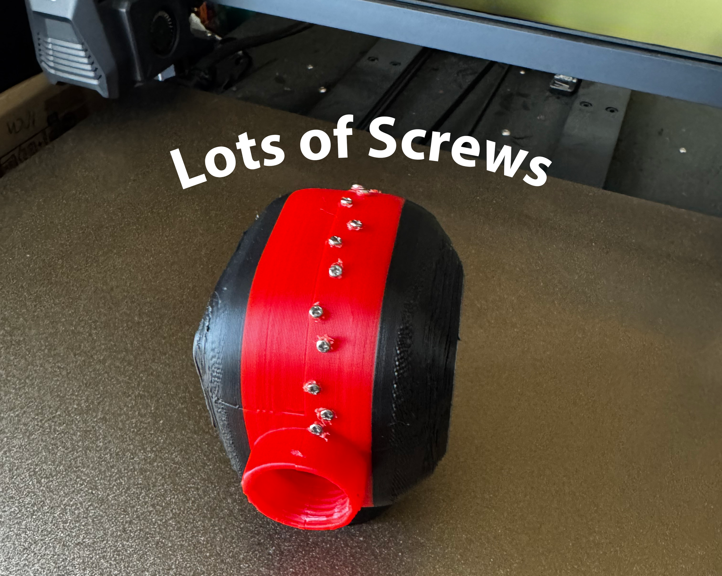
So, pretty much as soon as I let the full 60-80psi of my hose enter the part (the valve was closed), the two halves separated violently enough to break, which I kinda expected since the only thing holding it together was friction, but I didn’t expect it to actually break.
Solution
As the video shows, it didn't work perfectly since water is spraying at the top in the front, but that itself is a success,
especially because the water flowing up the front is under pretty high pressure. This suggests that if I seal those holes, the whole system will likely work perfectly. The best part is that there's no water coming out the bottom, meaning the valve is sealed and the o-ring worked.
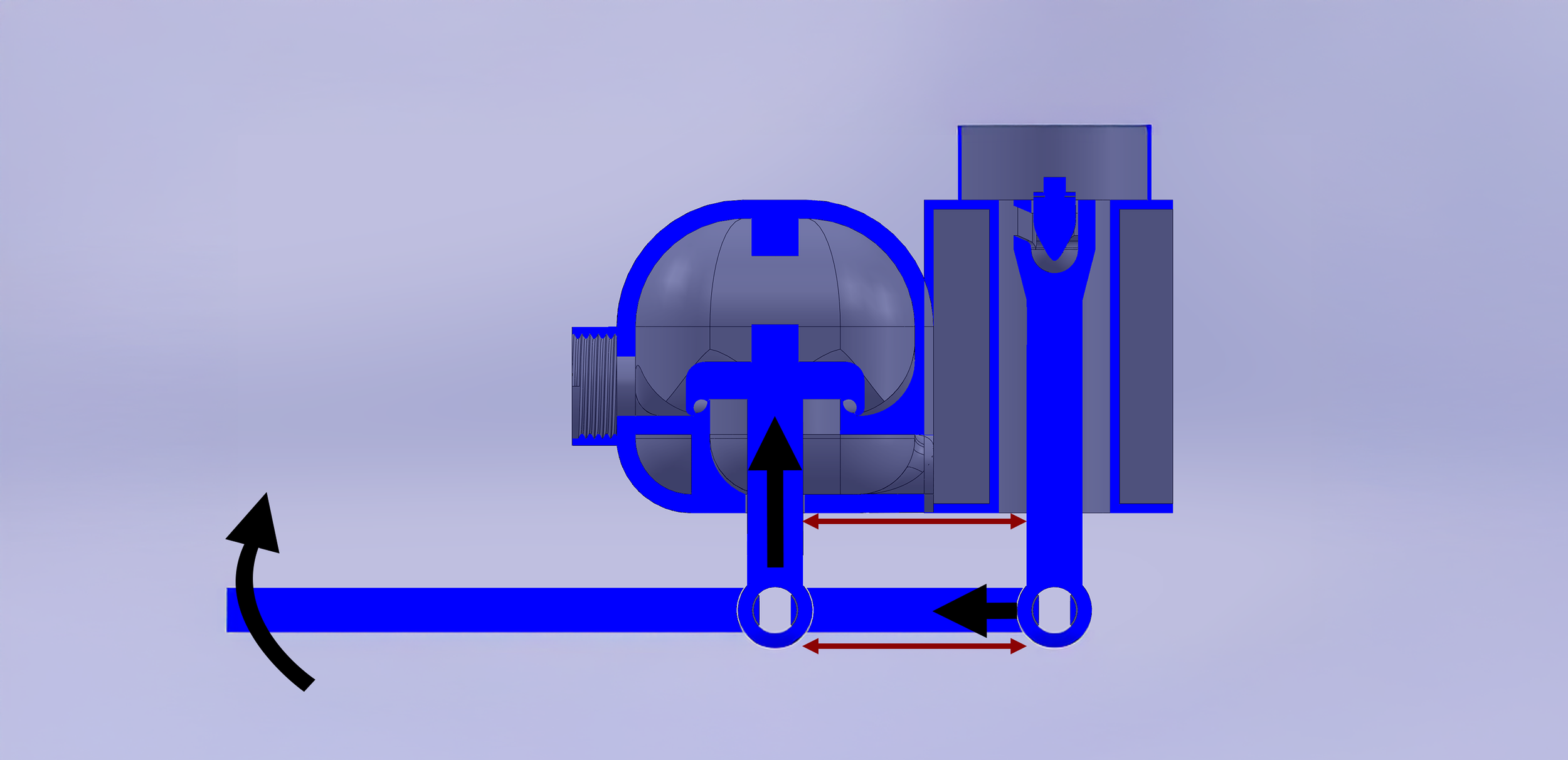
I was fairly happy with that progress, so I took a moment to think about it, but I couldn’t figure out how to seal the holes. Instead, I chose to work on the auto-release mechanism, designed the entire mechanism, and then realized that trigonometry prevents me from using it at all.
So the length of the two red arrows is the same, and the black arrows indicate the motion
as you can see pushing up the lever would cause the second post to
move and twist and this is not gonna work
So, in an effort to solve this problem, I decided to splurge on a real gas nozzle to study how it works and copy it. I figured it would be too costly and impractical for the final version. But after giving Amazon $40, I am now the proud owner of a real gas nozzle.
Not only that, but I also found out that it’s even cheaper on AliExpress and Alibaba, meaning it might be viable to use in the final product.
It might work?
After discovering that something that could mean over 60 hours of work turned out to be for nothing, I realized I had no idea if that was actually the case. So, I decided to order it and test.
Worked flawlessly!!!
except...
Problem 1: It’s Not New
At the end of the day, putting a gas hose in a pool isn’t an invention—it’s a repurpose. That doesn't sit right with me. I want to build something original.
Problem 2: Wrong Activation Method
The valve didn’t function as I wanted. I envisioned a press-down top where the only thing the user needs to do is press down—simple and intuitive. That wasn’t possible without another mechanism.
Problem 3: Not Adjustable
Adjustability was one of my top priorities, and this version didn’t offer any. That was a major limitation.
Problem 4: Weak Hose Connection
The attachment to the hose was weak. It just barely held on, and that’s not good enough for a finished product.
Each of these issues pushed me to keep going and work toward something better.
Problem 2:
My first thought was to use a gear ratio for opening and locking. I even went as far as to create a 3D model to validate it; here it is.
This was beyond awful. The first time I attempted to print it, I experienced
a print failure. On top of that, the simulation results indicated that it
probably wouldn't work anyway, so I went back to the drawing board.
After that horrendous flop, I figured out that the locking mechanism can actually be activated by pushing straight down at a specific angle. I don’t need a special mechanism to create a twisting force—just a direct, straight force does the job. This persisted to the final design.
This is a sectional view of the final design for the mechanism. While it may appear more complicated
than the original, it’s the result of addressing all the small issues. (The original design would have had to
overcome issues as well, making it more complicated.)
Problem 3:
I wanted it to be adjustable, so I decided to go with a slider, and here it is.
This part changed the least throughout the process, it's almost identical to what’s on the final prototype.
This means that instead of only being able to fill your pool up to 6 inches below the edge, you can now fill it anywhere from 0.25 inches to 7 inches, and up to about 21 inches with an upcoming revision (which will be included with the product at launch).
Problem 4:
Originally, I thought this was going to be the hardest problem, but it turned out to be pretty manageable. It only took eight iterations to get the first side right, and I had the other side figured out by the second iteration. So surprisingly, this part was actually pretty easy.
This entire part was designed in a single day and technically worked on the first try.
After this part was completed, it was time for the final bucket test, and here it is.
Please note that this is not the final product. The final version will not leak out the back as
shown here. It's nearly impossible to get a decent seal with a 3D printer using a 0.8 mm nozzle.